Operator’s Handbook for the Startwell Starter
Getting Started
Thank you for purchasing the Startwell Mechanical Starter.
The starter should provide you with thousands of maintenance free engine starts. If for any reason you do experience any problems with your starter please write, or telephone us directly, contact your local agent who will be happy to resolve your problem.
This booklet provides you with all the information you should need to install and operate your Startwell Starter.
Contents of Box
- Starter
- Winding Handle,
- Getting Started Operator’s Handbook,
- Operating Instruction Stickers, as required
- Check Card
- Bolts/Nuts/Spacer, as required
| 1 | Front Housing | 5 | Reset Knob | 9 | Drive Gear | 13 | Circlip |
| 2 | Viewing Window | 6 | Input Adaptor | 10 | Spacer Shims | 14 | Drive Ratchet |
| 3 | Body | 7 | Rear Housing | 11 | Drive Shaft | 15 | Lock |
| 4 | Trip Lever | 8 | Bevel Pinion | 12 | Drive Nut | 16 | Drive Pinion |
Your Starter Type
You can check the starter type from the name plate situated at the top of your Startwell Starter.
Installation
The Startwell Starter is easy to install and operate. It requires no special skills or tools. You should, however, still read the following step-by-step instructions before fitting or operating the starter.
Rotation:
a) The SNC, SDC, SDCH, SXC, SXCH and SSXC starter ranges are designed for anti-clockwise rotation engines only, viewed from the flywheel end. In other words, the starter replaces clockwise rotation electrical, pneumatic or hydraulic starters. (See Appendix II). See Appendix V for modified operation of anticlockwise starter.
Engine Space:
Check that you have sufficient room on the engine crankcase to fit the starter. (See Appendix I)
Replacing the Original Starter:
Remove the existing electric, pneumatic or hydraulic starting device, ensuring that you retain any spacers already present, unless the starter model that you have already has a spacer included with it.
Make sure that while removing the old starter you do not disconnect the fuel shut-off valve. On some applications there may be an electrical engine shut-off valve. This can either be operated by direct supply from the battery or converted to manual shut-off.
Startwell Design:
You may find when replacing your current starter with the Startwell Starter that there is a difference between the numbers of teeth on the two pinions. This is a design feature adapted to make a larger body diameter Startwell Starter replaces a smaller diameter electric starter. This is achieved by offsetting the spigot and mounting holes of the starter from its centreline and increasing the number of teeth to compensate for this.
Pre Installation checks:
The Startwell Starter is designed so that when installed on the engine, in the unwound position, there is between 3 and 5 mm clearance between the pinion face and the flywheel ring gear. To ensure that the clearance is correct, press the ‘check card’ (provided) against the ring gear and ensure the flange mounting face sits in the green area. (See Fig. 1)
Alternative:
measure the mounting face to pinion face dimension ‘X’, and the mounting face to ring gear depth ‘Y’. The distance Y-X should be between 3 and 5 mm. (See Fig 2)
Final Preparation:
To complete the installation tighten the nuts or bolts (whichever is appropriate for your application) to the torque recommended by the engine manufacturer.
The starter is assembled so that in the majority of applications the winding handle is in a position suitable for you to wind the starter comfortably. If this is not the case the angle of the winding handle position can be changed to suit your needs. See Position Code Procedure, page.8.
Operation
- If the starter is fitted on a tractor or mechanical handling vehicle, such as a fork lift truck or a loader, ensure that the gearbox is in the neutral position.
- Ensure that the fuel is turned OFF.
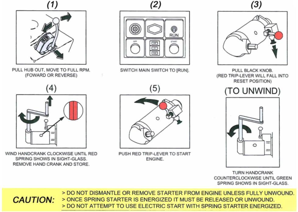
- Using the winding handle, rotate the winding adaptor until the WHITE spring is visible in the window. Move the trip lever to the trip position.
- The engine will rotate but not start. This will ensure that the starter is operating normally.
- Check the fuel valve is in the ‘ON’ position and that fuel is reaching the fuel pump.
- Adjust the throttle to between 1/2 and 3/4 open.
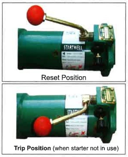
- The trip lever (with the red knob), of the starter, must be in an upright position. If this is not the case, pull the reset knob (black). The trip lever will immediately spring to its upright position.
- When starting an engine fitted with an in-line pump for the first time, it may be necessary to press the excess fuel button on the pump.
- Fit the Cranking handle and wind the handle in a clockwise direction until red or white springs are visible through the inspection windows (See Appendix II for number of turns). With the white spring visible the starter is ready to start a warm engine. With red springs visible the starter is ready to start a cold engine.
- To start your engine, push the trip lever down through 90°.
- If the engine does not start repeat the above steps. Your engine will normally start within three attempts.
Unwinding – Set Trip Lever to Vertical Position
If after fully winding the starter it is necessary to unwind and de-energize it, simply unwind the crank handle in an anti-clockwise direction. It may be necessary, at first, to exert extra force to disengage the clutch. Continue unwinding until green springs are visible through the inspection windows. At this point the starter pinion will also retract to its rest position.
Slow Engine Cranking
The Startwell Starter can be used to slowly crank an engine, for the adjustment of tappets, pump timing or equipment coupled to your engine. With the red trip lever in the upright (downward for anticlockwise starter) position turn the winding handle clockwise for two turns. This will engage the pinion with the ring gear. Now trip the lever through 90°. The black reset knob will pull in and lock the red trip lever in this position. The engine can now be turned slowly with the winding handle, and any adjustments, to the engine, may be made. Once slow cranking is completed you should pull the black reset knob and either fully wind to start the engine (see Operation) or unwind to disengage the pinion (see Unwinding).
Dual Starting Engines (See Appendix IV for important information)
Where the engine has the facility to be operated using two starters (electric starter and the Startwell starter), the Startwell starter must have its pinion disengaged from the engine flywheel when the alternative starter is being used. The pinion is disengaged by turning the winding handle in an anticlockwise direction, until no further unwinding is possible. This also applies to vehicles fitted with a Startwell starter that are being ‘bump’ started e.g. forklifts, tractors.
Cold Starting
When starting at ambient temperatures below 0°C, it will be necessary to use some form of starting aid. Starting can be achieved through various forms of ether-assisted aids which are available in aerosol cans or as auto start kits.
To cold start proceed with normal starting operation. Prior to tripping, spray the ether into the air intake, or if your engine is fitted with an auto start kit inject the ether inside the inlet manifold. If the engine fails to start, repeat the whole operation immediately. The engine should now start.
Trouble Shooting
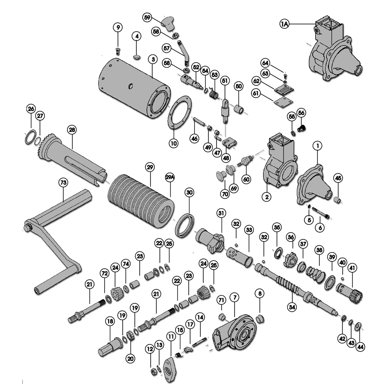
(Components described in this section are illustrated in ‘The Startwell Starter, pg.3)
Operation of your Startwell Starter should be trouble free, as long as the starter has been fitted correctly (see installation), and the correct engine and starter operation is adhered to (see operation). If a problem does occur it is often possible for the operator to identify and correct the situation.
Faulty Winding Mechanism
On turning the winding handle two turns in a clockwise direction the winding adapter should rotate smoothly, thus causing the drive pinion to move forward and engage with the flywheel ring gear. Further rotation should cause the spring pack to gradually compress as viewed through the body inspection window.
| FAULT | CAUSE | ACTION |
|---|---|---|
| Winding adaptor is jammed so that cranking handle will not turn | the bevel pinion is broken and is locking the drive gear rotation | The bevel pinion must be replaced and the drive gear checked for damage |
| Winding adaptor’s rotation is ‘stiff’ or not-smooth | the meshing between the bevel pinion and drive gear is too tight | Shims (part no. 20026) must be added or removed from between the rear housing bearing and the drive gear |
| Winding adaptor rotates but the spring core does not compress and the pinion and core pack does not rotate. | the bevel pinion or the input shaft is broken | The bevel pinion or input shaft must be replaced |
| Winding the adaptor does not cause the spring pack to compress or the drive pinion to move forward to engagement (the drive pinion does however rotate) | the drive ratchet is broken or the circlip has come loose / the pinion is jammed on the drive shaft due to burring on five start thread or due to excessive rust | Fit new ratchet or circlip as appropriate / Burring can be removed with a grinding stone or a new drive shaft fitted |
| Operation is normal up to compression of spring pack, but starter then discharges prematurely before pack is fully compressed | the lock height is incorrect / the lock and/or ratchet are worn | Adjust lock to correct height, using lock height gauge (part no. ST 123A) / Replace worn component(s) |
Jammed Starter
| FAULT | CAUSE | ACTION |
|---|---|---|
| The starter jams during compression of the spring pack or fails to discharge on tripping. | The drive shaft or drive nut threads are worn causing the ball bearings to jam between the nut and the shaft. | Set Trip Lever to vertical position. Turn the Winding Adaptor anti-clockwise, until the green spring is visible through the window. |
IF the starter still cannot be discharged, place the starter in a strong wooden box and contact Startwell for further instructions.
Position Code Procedure
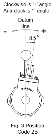
The winding handle position relative to the angle of the nosepiece can be rotated through 360°, in 8.5° steps, to achieve the best winding position. Starters are made to a pre-set position in the factory that should be right for your application. If, however, you require an alternative position follow the steps below:
- For the factory built position code, refer to outline or general arrangement drawing.
- For an alternative position code, decide on the angle between the release lever and input adaptor to suit your application (e.g. your selected angle = +10°).
- Select the nearest position code from the table below (e.g. 8.5°+ = 2B).
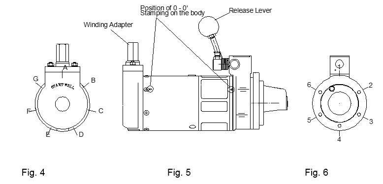
- To achieve the selected (2B) position code, align the hole next to the letter ‘0’ at the front end of the body, against the hole designated ‘2’ on the front housing. Use the correct through bolt to secure the front mounting bracket, the housing and the body in this position. (Note: For starter without separate mounting bracket secure housing assembly to the body).
- Place the rear housing on the body and align the radial hole ‘B’ against the letter ‘0’ on the body. Secure the body and the rear housing in this position.
- Fit the remaining screws and tighten to a torque of 6-8 Nm.
Position Code Table
| Code | Angle ‘+’ | Code | Angle ‘-‘ |
|---|---|---|---|
| 1A | 0 | 1A | 0 |
| 2B | 8.6 | 6G | 8.6 |
| 3C | 17.1 | 5F | 17.1 |
| 4D | 25.7 | 4E | 25.7 |
| 5E | 34.2 | 3D | 34.2 |
| 6F | 42.9 | 2C | 42.9 |
| 1G | 51.4 | 1B | 51.4 |
| 2A | 60 | 6A | 60 |
| 3B | 68.6 | 5G | 68.6 |
| 4C | 77.1 | 4F | 77.1 |
| 5D | 85.7 | 3E | 85.7 |
| 6E | 94.2 | 2D | 94.2 |
| 1F | 102.9 | 1C | 102.9 |
| 2G | 111.6 | 6B | 111.6 |
| 3A | 120 | 5A | 120 |
| 4B | 128.6 | 4G | 128.6 |
| 5C | 137.1 | 3F | 137.1 |
| 6D | 145.7 | 2E | 145.7 |
| 1E | 154.2 | 1D | 154.2 |
| 2F | 162.9 | 6C | 162.9 |
| 3G | 171.4 | 5B | 171.4 |
| 4A | 180 | 4A | 180 |
Note: The six through holes on the front housing are designated by numbers 1 to 6 clockwise, looking from the rear of the housing (fig.6). The seven radial tapped holes on the rear housing are designated by letters A to G clockwise, looking from the rear of the housing (fig.4). On the starter body, only two of the holes at either end are in line. These are marked with ‘O’ next to each hole (fig 5).
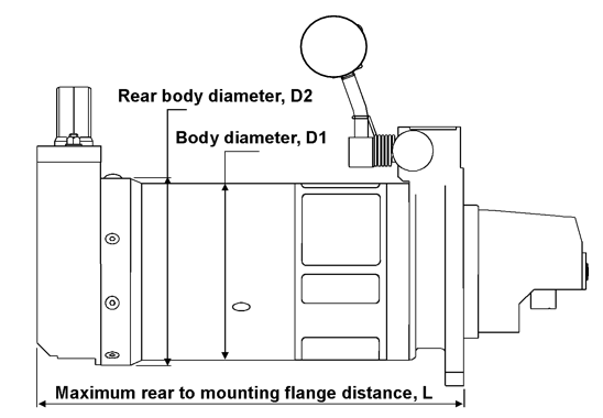
| L(mm) | D1(mm) | D2(mm) | |
|---|---|---|---|
| MINI | 259 | 110 | 114 |
| MIDI | 285 | 115 | 118 |
| HEAVY DUTY | 285 | 115 | 127 |
| MAXI | 329 | 117 | 130 |
| MAXI HD | 329 | 133 | 136 |
| SUPER MAXI | 346 | 133 | 140.5 |
| MINI | MIDI | MIDI HD | MAXI | MAXI HD | SUPER MAXI | |
|---|---|---|---|---|---|---|
| Clock Model | SNC | SDC | SDCH | SXH | SXCH | SSXC |
| A/CLock Model | SNA | SDA | SDAH | SXA | SXAH | SSXC |
| Mounting Flange | SAE1 SAE4 | SAE1 SAE2 SAE3 | SAE1 SAE2 SAE3 | SAE1 SAE2 SAE3 | SAE1 SAE2 SAE3 | SAE1 SAE2 SAE3 |
| Capacity – Litre / Cylinder | 0.5 | 1.1 | 1.3 | 1.5 | 2 | 2.3 |
| Capacity – Max. No. of Cylinders | 4 | 6 | 6 | 6 | 6 | 6(8) |
| Max Torque – Pinion (Nm) | 123 | 156 | 171 | 171 | 198 | 199 |
| Max Torque – Winding (Nm) | 81 | 87 | 95 | 95 | 102 | 109 |
| Weight (Kg) | 12 | 16 | 18 | 20 | 22 | 25 |
| Turns to Fully Wind | 7.5 | 10 | 10 | 13.5 | 14 | 16 |
| 1 | Mounting Flange | 18 | Input Adaptor | 36 | Drive Ratchet | 54 | ‘O’ Ring |
| 1A | Mounting Bracket | 19 | Friction Washer | 37 | Spring Locating Disc | 55 | Lock Washer |
| 2 | Lock Housing | 20 | Input Ratchet | 38 | Return Spring | 56 | Lock Stop |
| 3 | Body | 21 | Input Shaft | 39 | Spring Locator | 57 | Release Lever |
| 4 | Window | 22 | Thrust Washer | 40 | Ball Bearing | 58 | Lock Nut |
| 5 | Washer | 23 | Bush | 41 | Drive Pinion | 59 | Hand Grip |
| 6 | Screw | 24 | Input Gear | 42 | Thrust Washer 43/44 | 60 | Reset Assembly |
| 7 | Rear Housing | 25 | E-Clip | 43 | Shim | 61 | Gasket |
| 8 | Plug | 26 | Shim | 44 | Belville Washer | 62 | Cover Plate |
| 9 | Screw | 27 | ‘O’ Ring | 45 | Bush | 63 | Spring Washer |
| 10 | Shim | 28 | Drive Gear | 46 | Swivel Pin | 64-68 | Screw |
| 11 | Support Plate | 29 | Drive Spring | 47 | Lock Pin | 69 | Bellows |
| 12 | Nut | 30 | Drive Ring | 48 | Lock | 70 | Hand Grip |
| 13 | Lock Washer | 31 | Drive Nut | 49 | Bush | 71 | Rear Plug |
| 14 | Stud | 32 | Ball Bearing | 50 | Bush | 72 | Distance Collar |
| 15 | Catch Spring | 33 | Cage | 51 | Link Assembly | 73 | Cranking Handle |
| 16 | ‘O’ Rings | 34 | Drive Shaft | 52 | Release Shaft | 74 | Distance Piece |
| 17 | Catch | 35 | Circlip | 53 | Return Spring |
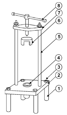
Parts List For Tool kit
| Part Number | Part Description | |
|---|---|---|
| 1 | SWT 138/2 | Base Plate Feet |
| 2 | SWT 138/1 | Base Plate |
| 3 | SWSH | Socket Headed Screw |
| 4 | SWT 121 | Spacer |
| 5 | SWT 138/3 | Pillar |
| 6 | SWT 122 | Press Tool |
| 7 | SWT 138/4 | Pressure Plate |
| 8 | SWT 138/5 | Handle Assembly |
| SWT 123 | Lock Setting Gauge | |
| SWC P1 | External Circlip Pliers |
Appendix IV: Important Operating Instructions
Storage Mounting
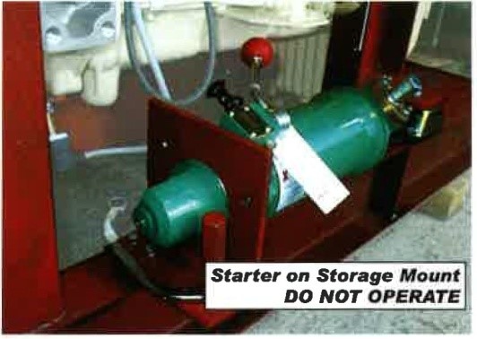
It has come to our attention that on some vessels during regular periodic maintenance on the emergency Gen-set, the Startwell stand-by starter types SXC047 and SXCH047 are being tested when fitted on the storage bracket next to the engine.
This is causing serious internal damage to the starter and resulting in premature failure when later used on the engine.
Any damage caused by this action will not be covered under warranty. This bulletin does not apply to starters fitted permanently on any engine
Instructions for ‘Dual -Start Engines’
On engines fitted with dual starting system, such as electrical and manual starter, the manual starter must not remain engaged with Flywheel when starting with the electric starter. Or when the engine starts automatically with electrical starter (such as on a ships emergency generator)
To ensure the starter is not engaged, leave the trip lever in the trip position when the starter is not in use. This will ensure that the starter pinion is not engaged with the engine flywheel
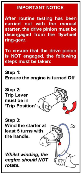
Appendix VI: Routine Testing of Startwell Starter
It is important to establish that the pinion has returned to its rest position (out of Engagement) after routine testing has been carried out. See instructions on the right.
Whilst winding, if the engine DOES rotate then please follow the procedure below;
- With the ‘Trip’ lever this time in ‘Reset Position’ unwind the starter anti-clockwise 2-3 turns
- The Pinion will retract back to its Rest position (out of Engagement).
- Once the above steps have been carried out, with the Trip Lever in ‘Trip’ position, wind the starter clock-wise to ensure the Pinion is disengaged with flywheel ring-gear.
- Rotate the winding handle a few more turns.
- Observe that the GREEN spring is rotating and there is no rotational movement of the engine crankshaft.
- If the engine crankshaft rotates, remove the starter from the engine.
- Contact Startwell Engineering, supplying full details by email to info@startwell.com
